Resistor color codes
How to read Resistor Color Codes
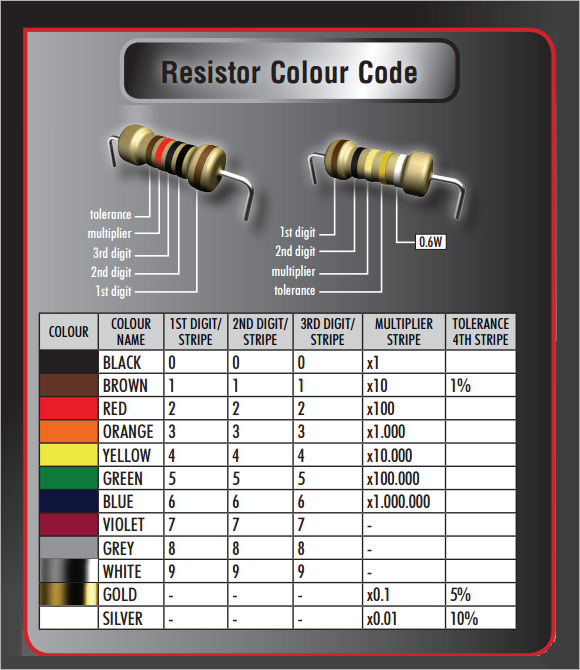
4- Band Code 5- Band Code RESISTOR COLOR CODE GUIDE 2 0 x10,000 10% 20 x 10,000 = 200,000 1,000 = 1K Resistor = 200 K with a 10% Tolerance+-First Band Second Band Multiplier Band Tolerance Band Equation The Gold or Silver band is always placed to the right. The resistor value is read from the left to right. Reading and Determining the Resistor Value Hold the resistor with the gold or silver band to the right and read the color codes from the left to the right. Select the color codes from the bands on the resistor. Read the colors from left to right.
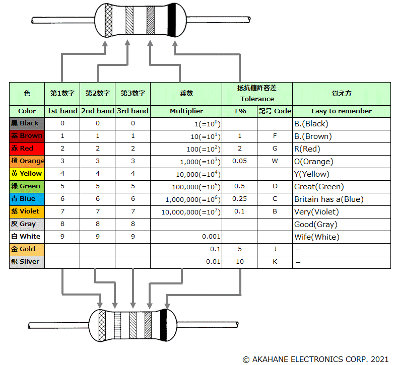
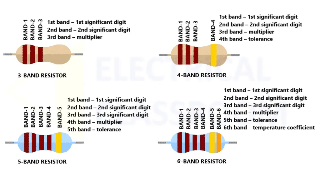
Resistor Color Code Identification While these codes are most often associated with resistors, then can also apply to capacitors and other components. The standard color coding method for resistors uses a different color to represent each number 0 to 9: black, brown, red, orange, yellow, green, blue, purple, gray, white. Resistor Color Code. Up to six color bands are used for resistors. The most common is a four-band color code, in which the first and second bands represent the first and second significant digit of the resistance value, the third band is the decimal multiplier and the fourth band indicates the tolerance. This resistor color code calculator is designed to find the resistance and tolerance values of through hole resistors.
The 4-band code is used for marking low precision resistors with 5%, 10% and 20% tolerances. Identifying the value will become easy with a little practice, as there are only a few simple rules to remember:
- The first two bands represent the most significant digits of the resistance value. Colors are assigned to all the numbers between 0 and 9, and the color bands basically translate the numbers into a visible code. Black is 0, brown is 1, red is 2 and so on (see the color code table below). So, for example, if a resistor has brown and red as the first two bands, the most significant digits will be 1 and 2 (12).
- The third band indicates the multiplier telling you the power of ten to which the two significant digits must be multiplied (or how many zeros to add), using the same assigned value for each color as in the previous step. For example, if this band is red (2), you will multiply it by 102 = 100 (or add 2 zeros). So, for the resistor we used in the previous example, the value would be: 12 x 100 = 1200Ω (1.2kΩ).
Note: If the multiplier band is gold or silver, the decimal point is moved to the left by one or two places (divided by 10 or 100). - The tolerance band (the deviation from the specified value) is next, usually spaced away from the others, or it's a little bit wider. A color is assigned to each tolerance: gold is 5%, silver is 10%. 20% resistors have only 3 color bands - the tolerance band is missing.
The standard resistor color code table:
| Color | 1st digit | 2nd digit | 3rd digit* | Multiplier | Tolerance | Temp. Coef. | Fail Rate |
|---|---|---|---|---|---|---|---|
| Black | 0 | 0 | 0 | x100 | |||
| Brown | 1 | 1 | 1 | x101 | ±1% (F) | 100 ppm/K | 1% |
| Red | 2 | 2 | 2 | x102 | ±2% (G) | 50 ppm/K | 0.1% |
| Orange | 3 | 3 | 3 | x103 | 15 ppm/K | 0.01% | |
| Yellow | 4 | 4 | 4 | x104 | 25 ppm/K | 0.001% | |
| Green | 5 | 5 | 5 | x105 | ±0.5% (D) | ||
| Blue | 6 | 6 | 6 | x106 | ±0.25%(C) | ||
| Violet | 7 | 7 | 7 | x107 | ±0.1% (B) | ||
| Gray | 8 | 8 | 8 | x108 | ±0.05%(A) | ||
| White | 9 | 9 | 9 | x109 | |||
| Gold | x0.1 | ±5% (J) | |||||
| Silver | x0.01 | ±10% (K) | |||||
| None | ±20% (M) |
* 3rd digit - only for 5-band resistors
So, for a 560 ohm, 5% resistor the color stripes will be green, blue, brown and gold. Green and blue are the first significant digits (56); brown is the multiplier (101 = 10) and gold is the tolerance (5%). 56 x 10 = 560Ω.

If the 3rd band would be red instead of brown, the multiplier would be (102 = 100) instead of 10 and the resistor value would be 56 x 100 = 5600 ohms = 5.6 k ohms.
If the multiplier band is gold or silver, then the decimal point is moved to the left one or two places (divided by 10 or 100). For example, a resistor with green, blue, silver and gold rings has a value of 56 x 0.01 = 0.56Ω.
The 5-band code
The 5 band code is used for marking high quality, precision resistors with 2%, 1% or lower tolerances. The rules are similar to the previous system; the only difference is the number of digit bands. The first 3 bands will represent the value, the 4th band will be the multiplier and the 5th stripe will give us the tolerance.
Optional band

A few resistors have an additional band - often giving beginners a bit of trouble - indicating either the reliability or the temperature coefficient.

The reliability band specifies the failure rate per 1000 hours (assuming that a full wattage being applied to the resistor). This stripe is found primarily on 4-band resistors made for military applications and seldom used in commercial electronics.
The temperature coefficient is more commonly marked, especially on quality 5-band resistors, as it starts to become an important factor for precision components. For a resistor with temperature coefficient of 200 ppm, for example, a change in temperature of 50°C causes a value change of 1%. The most common values for this band are presented in the color chart above.
Examples:
Four band code:
Green, blue, red, with silver tolerance band: 56 x 100 = 5.6 kohms, with a tolerance of 10%
Brown, black, orange, gold tolerance band: 10 x 1000 = 10000 ohms (or 10K ohms), with a tolerance of 5%
Red, red, brown, silver tolerance band: 22 x 10 = 220 ohms (220 ohms), with a tolerance of 10%
More 4 band resistor color code examples: E12 and E24 series.
Five band code:
Blue, brown, white, brown, red tolerance band: 619 x 10 = 6190 ohms (6.19K ohms), with a tolerance of 2%
Red, red, brown, black, with a brown tolerance band: 221 x 1 = 221 ohms, with a tolerance of 1%
Brown, black, black, red, with a brown tolerance band: 100 x 100 = 10000 ohms (10.0K), with a tolerance of 1%
Standard EIA Decade Resistor Values
Resistors are available in standard values such as 1K, 2.2K, 4.7K, and so on. The two most common standards are the E12 and E24. You will notice that in the E12 series each succeeding value falls within +/- 10% of the previous value. The E24 range includes all of the E12 values, plus a further 12 to enable the selection of more precise resistances.
The E6 (20%) range is a subset of the E12 (10%) range and the E12 range is a subset of the E24 (5%) range. Similarly, the E48 (2%) range is a subset of the E96 (1%) range and the E96 range is a subset of the E192 (0.5% or less) range. Note, that the E24 range is technically also a subset of the E48 range, however, because of the different number of digits used for representation and rounding errors, the corresponding values in the two series do not match.
E6 series: (20% tolerance)
10, 15, 22, 33, 47, 68
E12 series: (10% tolerance) - examples...
10, 12, 15, 18, 22, 27, 33, 39, 47, 56, 68, 82

E24 series: (5% tolerance) - examples...
10, 11, 12, 13, 15, 16, 18, 20, 22, 24, 27, 30, 33, 36, 39, 43, 47, 51, 56, 62, 68, 75, 82, 91
E48 series: (2% tolerance) - examples...
100, 105, 110, 115, 121, 127, 133, 140, 147, 154, 162, 169, 178, 187, 196, 205, 215, 226, 237, 249, 261, 274, 287, 301, 316, 332, 348, 365, 383, 402, 422, 442, 464, 487, 511, 536, 562, 590, 619, 649, 681, 715, 750, 787, 825, 866, 909, 953
E96 series: (1% tolerance)
100, 102, 105, 107, 110, 113, 115, 118, 121, 124, 127, 130, 133, 137, 140, 143, 147, 150, 154, 158, 162, 165, 169, 174, 178, 182, 187, 191, 196, 200, 205, 210, 215, 221, 226, 232, 237, 243, 249, 255, 261, 267, 274, 280, 287, 294, 301, 309, 316, 324, 332, 340, 348, 357, 365, 374, 383, 392, 402, 412, 422, 432, 442, 453, 464, 475, 487, 491, 511, 523, 536, 549, 562, 576, 590, 604, 619, 634, 649, 665, 681, 698, 715, 732, 750, 768, 787, 806, 825, 845, 866, 887, 909, 931, 959, 976
Final thoughts
So, why all this trouble with color coding? The resistance value could be stamped or painted on the body of the through-hole resistor, no?
Yes, but the numbers would be quite small and difficult to read. If such a resistor is mounted with the marked side down, you cannot read its value unless you take it out of the circuit. Also, the markings would easily rub off or become smeared with time.
The resistor color code might seem a bit confusing and rather inconvenient at first, but most electronics hobbyists and technicians are surprised when they realize how quickly they've memorized the color chart without the use of mnemonics or other silly shortcuts.
The color code is quite intuitive, and after a brief familiarization period, instantly recognizing resistor values will come as second nature.
Definitions and Calculations
Resistor and Resistance
Resistor Color Code
A resistor is a passive electrical component that creates electrical resistance in electronic circuits. Resistors can be found in almost all electrical circuits. They are used for various purposes, for example, to limit electric current, as voltage dividers, to provide bias to active circuit elements, to terminate transmission lines, in resistor-capacitor circuits as a timing component... The list is endless.
The electrical resistance of a resistor or an electrical conductor is a measure of the opposition to the flow of electric current. The SI unit for resistance is the ohm. Any material shows some resistance except superconductors, which have zero resistance. More information about resistance, resistivity and conductance.
Resistor Tolerance
Of course, it is possible to make a resistor with very precise resistance, however, it will be insanely expensive. Besides, high precision resistors are relatively rarely used. There are very expensive resistors used for measurements. Here we will talk about inexpensive resistors used in electric circuits, which do not require high precision. In many cases, ±20% of precision is enough. For a 1 kilohm resistor, this means that any resistor with a value in the range of 800 ohms to 1200 ohms is acceptable. For some critical components, the tolerance can be specified as ±1% or even ±0.05%. At the same time, it is hard to find 20% resistors today — they were common at the beginning of the transistor radio era. 5% and 1% resistors are very common today. They were relatively expensive in the past, but not anymore.
Power Dissipation
When an electric current passes through a resistor, it is heated and the electrical energy is converted into the thermal energy, which it dissipates. This energy must be dissipated by the resistor without excessive raising its temperature. And not only its temperature but also the temperature of components surrounding this resistor. The power consumed by a resistor is calculated as
where V in volts is the voltage across the resistor of resistance R in ohms and I is the current in amps flowing through it. The power that a resistor can safely dissipate for an indefinite period of time without degrading its performance is called the resistor power rating or resistor wattage rating. Generally, the larger the resistor package, the more power it can dissipate. Resistors of different power ratings are produced, most commonly from 0.01 W to hundreds of watts. Carbon resistors are commonly produced in power ratings of 0.125 to 2 watts.
Preferred Values
Although it is possible to produce resistors of any value, it is more useful to make a limited number of components, especially considering that any manufactured resistor is subject to a certain tolerance. More precision resistor's costs are much higher than their less precise counterparts. Common logic dictates to choose a logarithmic scale of values so that all values are equally spaced on a logarithmic scale and match the tolerance of the range. For example, for a tolerance of ±10%, it makes sense to cover a decade (the interval from 1 to 10, 10 to 100, etc.) in 12 steps: 1.0, 1.2, 1.5, 1.8, 2.2, 2.7, 3.3, 3.9, 4.7, 5.6, 6.8, 8.2, then 10, 12, 15, 18, 22, 27, 33, 39, 47, 56, 68, 82. These values are called preferred values and are standardized as E series of preferred numbers, which are used not only for resistors, but also for capacitors, inductors, and Zener diodes. Each E-series (E3, E6, E12, E24, E48, E96, and E192) subdivides a decade into 3, 6, 12, 24, 48, 96 and 192 steps. Note that the E3 series is obsolete and is almost not used anymore.
Lists of E Series Values
E6 values (20% tolerance):
1.0, 1.5, 2.2, 3.3, 4.7, 6.8.
Resistor Color Code 2
E12 values (10% tolerance):
1.0, 1.2, 1.5, 1.8, 2.2, 2.7, 3.3, 3.9, 4.7, 5.6, 6.8, 8.2.
E24 values (5% tolerance):
1.0, 1.1, 1.2, 1.3, 1.5, 1.6, 1.8, 2.0, 2.2, 2.4, 2.7, 3.0, 3.3, 3.6, 3.9, 4.3, 4.7, 5.1, 5.6, 6.2, 6.8, 7.5, 8.2, 9.1.
E48 values (2% tolerance):
1.00, 1.05, 1.10, 1.15, 1.21, 1.27, 1.33, 1.40, 1.47, 1.54, 1.62, 1.69, 1.78, 1.87, 1.96, 2.05, 2.15, 2.26, 2.37, 2.49, 2.61, 2.74, 2.87, 3.01, 3.16, 3.32, 3.48, 3.65, 3.83, 4.02, 4.22, 4.42, 4.64, 4.87, 5.11, 5.36, 5.62, 5.90, 6.19, 6.49, 6.81, 7.15, 7.50, 7.87, 8.25, 8.66, 9.09, 9.53.
E96 values (1% tolerance):
1.00, 1.02, 1.05, 1.07, 1.10, 1.13, 1.15, 1.18, 1.21, 1.24, 1.27, 1.30, 1.33, 1.37, 1.40, 1.43, 1.47, 1.50, 1.54, 1.58, 1.62, 1.65, 1.69, 1.74, 1.78, 1.82, 1.87, 1.91, 1.96, 2.00, 2.05, 2.10, 2.15, 2.21, 2.26, 2.32, 2.37, 2.43, 2.49, 2.55, 2.61, 2.67, 2.74, 2.80, 2.87, 2.94, 3.01, 3.09, 3.16, 3.24, 3.32, 3.40, 3.48, 3.57, 3.65, 3.74, 3.83, 3.92, 4.02, 4.12, 4.22, 4.32, 4.42, 4.53, 4.64, 4.75, 4.87, 4.99, 5.11, 5.23, 5.36, 5.49, 5.62, 5.76, 5.90, 6.04, 6.19, 6.34, 6.49, 6.65, 6.81, 6.98, 7.15, 7.32, 7.50, 7.68, 7.87, 8.06, 8.25, 8.45, 8.66, 8.87, 9.09, 9.31, 9.53, 9.76.
E192 values (0.5% and lower tolerance):
1.00, 1.01, 1.02, 1.04, 1.05, 1.06, 1.07, 1.09, 1.10, 1.11, 1.13, 1.14, 1.15, 1.17, 1.18, 1.20, 1.21, 1.23, 1.24, 1.26, 1.27, 1.29, 1.30, 1.32, 1.33, 1.35, 1.37, 1.38, 1.40, 1.42, 1.43, 1.45, 1.47, 1.49, 1.50, 1.52, 1.54, 1.56, 1.58, 1.60, 1.62, 1.64, 1.65, 1.67, 1.69, 1.72, 1.74, 1.76, 1.78, 1.80, 1.82, 1.84, 1.87, 1.89, 1.91, 1.93, 1.96, 1.98, 2.00, 2.03, 2.05, 2.08, 2.10, 2.13, 2.15, 2.18, 2.21, 2.23, 2.26, 2.29, 2.32, 2.34, 2.37, 2.40, 2.43, 2.46, 2.49, 2.52, 2.55, 2.58, 2.61, 2.64, 2.67, 2.71, 2.74, 2.77, 2.80, 2.84, 2.87, 2.91, 2.94, 2.98, 3.01, 3.05, 3.09, 3.12, 3.16, 3.20, 3.24, 3.28, 3.32, 3.36, 3.40, 3.44, 3.48, 3.52, 3.57, 3.61, 3.65, 3.70, 3.74, 3.79, 3.83, 3.88, 3.92, 3.97, 4.02, 4.07, 4.12, 4.17, 4.22, 4.27, 4.32, 4.37, 4.42, 4.48, 4.53, 4.59, 4.64, 4.70, 4.75, 4.81, 4.87, 4.93, 4.99, 5.05, 5.11, 5.17, 5.23, 5.30, 5.36, 5.42, 5.49, 5.56, 5.62, 5.69, 5.76, 5.83, 5.90, 5.97, 6.04, 6.12, 6.19, 6.26, 6.34, 6.42, 6.49, 6.57, 6.65, 6.73, 6.81, 6.90, 6.98, 7.06, 7.15, 7.23, 7.32, 7.41, 7.50, 7.59, 7.68, 7.77, 7.87, 7.96, 8.06, 8.16, 8.25, 8.35, 8.45, 8.56, 8.66, 8.76, 8.87, 8.98, 9.09, 9.20, 9.31, 9.42, 9.53, 9.65, 9.76, 9.88.
Resistor Marking
Large resistors, as shown in the picture, are usually marked with numbers and letters and their reading is easy. However, the value cannot be easily printed even using modern printing technology on small resistors (and other electronic components), especially if they are cylindrical. Therefore, during the past 100 years color bands were used for marking components. The electronic color code for this purpose was introduced in early 1920. Color codes are used not only for resistors but also for capacitors, diodes, inductors, and other electronic components.
Resistor Color Code
Up to six color bands are used for resistors. The most common is a four-band color code, in which the first and second bands represent the first and second significant digit of the resistance value, the third band is the decimal multiplier and the fourth band indicates the tolerance. There is a small, sometimes poorly distinguishable gap between the third and fourth band that helps distinguish the left and right side of the symmetrical component. 20% resistors are usually marked with only three bands — they do not have a tolerance band. Their bands mean digit, digit, multiplier.
For 2% or more precision resistors, five or more bands are used and the first three bands represent the resistance value. The last band in 6-band marking represents the temperature coefficient in ppm/K (parts per million per kelvin). The picture above represents the color marking principle.
Bands are read from left to right. They are usually grouped together close to the left end. If there is a visible gap between the last color band and other bands, then it shows the right side of the resistor. Also, silver or gold bands (if any) are always on the right side. When you determined the value from the color bands, compare it to the preferred value charts. If it is not there, then try to read from another end. Note that in this calculator color marking is made according to the international standard IEC 60062:2016.
Click or tap the links to view examples of color marking:

10 kohms ±20%, 12 ohms ±20%, 15 MΩ ±1%, 18 MΩ ±2%, 22 kohms ±10%, 27 ohms ±5%, 33 kohms ±5%, 39 MΩ ±0.5%, 0.47 ohms ±0.25%, 0.56 ohms ±0.1%, 68 ohms ±0.05%, 0.82 ohms ±20%
Numerical Marking
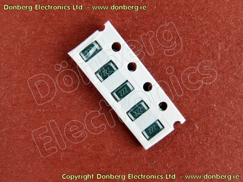
Numerical values are printed on the surface mount resistors (SMT — surface-mount technology or SMD — surface-mount device) of larger sizes and on larger axial-lead resistors. Because the space for marking is very small, it is sometimes not easy to read and understand the resistor value. The marking is mostly used for servicing because during production the resistors are fed into the surface mounting machines in tapes that are suitably marked. Many, especially small SMD resistors are not marked at all and once they are dropped from tapes, the only way to find their resistance is measurement.
Several systems are used for marking: three or four digits, two digits with a letter, three digits with a letter, the RKM code, and other systems. If you see only three digits, they represent the significant figures and the third is a multiplier. For example, 103 on an SMD resistor represents 10 × 10³ = 10 kΩ.
The four-digit system is used for high-tolerance resistors, for example for E96 or E192 series resistors. For example, 2743 = 274 × 10³ = 274 kΩ.
For smaller resistors, another system can be used. For example, for E96 series two digits plus one letter is used. This system can save one character comparing to the four-digit system. That is because E96 contains less than 100 values, which can be represented by two numbers if they are numbered sequentially, that is 01 — 100, 02 — 102, 03 — 105, etc. A letter represents the multiplier. Note that manufacturers often use their own systems. Therefore, the best way to determine the resistance is always measuring with a multimeter.
In the RKM Code, also called “R notation” a letter representing the resistance unit is placed instead of a decimal separator, which may not be printed reliably or just disappear on components or duplicated documents. Besides this method allows using fewer characters. For example, R22 or E22 means 0.22 ohm, 2K7 means 2.7 kiloohms and 1M5 means 1.5 megohms.
Resistance Measurement
Resistance can be measured with an analog (with a needle) or digital ohmmeter or multimeter with resistance measurement function. To measure resistance, connect the probes to the resistor leads and read the value. It is sometimes possible to measure resistance without removing a resistor from the circuit. However, you must disconnect the circuit power and discharge all capacitors before connecting the multimeter to the circuit being measured.
A multimeter can be used not only for measuring the resistance of resistors but also contact resistance of various switching components like relay or switches. For example, you can determine if a mouse button needs replacement by means of measuring its resistance preferably with an analog multimeter or a digital meter with an analog bar display. The analog bar graph is useful when performing diagnostic or making adjustments. The bar graph acts as a needle in an analog meter and can show fluctuating resistance when a digital display with blinking digits would be completely useless. With this kind of meter, you can easily find many intermittent problems, for example, bouncing contacts of a vibrating relay.
In conclusion, there are several examples: