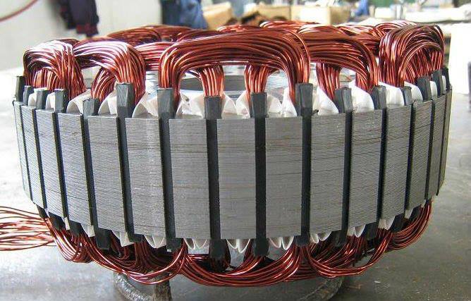
So you just burned your motor or you want to rewind your motor for more power/torque, but are confused as to how to wind the motor. Just enter the no of poles ( the no of stator arms) and the no of magnets in this calculator and it will provide a winding schematic.


If the copper loss is too high, select a winding distribution that is more efficient. In order to calculate the copper loss, you need to know the full-load current. To calculate that, you need all of the design characteristics of the motor including stator and rotor resistance and leakage reactance, magnetizing reactance and iron loss. Rewinding and Renovation of the Electric Motor: Hello, i am Niko, memeber of RoboSap team. In this instructables i will show you, how to rewind and renovate old electric single phase electric motor.I bought this electric motor on garage sale. It was cheap and we known that motor. The three-phase induction motor is the easiest motor of this type to understand so these notes start with that type. The single-phase induction motor is more subtle and less efficient. It is discussed later. The magnetic field in the air gap from the voltage applied to the stator: The stator has three sets of windings.
The no of poles/stator arms of the motor are always in the multiples of 3 and hence the motor has 3 phases. Each phase is winded separately. If you mark any stator arm as phase one, then the next stator arm of the same phase can be obtained by adding 3 to the first stator arm.
So you just burned your motor or you want to rewind your motor for more power/torque, but are confused as to how to wind the motor. Just enter the no of poles ( the no of stator arms) and the no of magnets in this calculator and it will provide a winding schematic. Motor Efficiency Improvement EPACT was passed in 1992 but motor efficiency provisions took effect in 1997. Commercial, institutional and, particularly, industrial operations use substantial amounts of power for electric motors. Although “high” or “premium” efficiencies may have only a few percentage points better.
So stator arms 1, 4,7,10…ect belong to one phase. Similarly stator arms 2,5,8,11…etc belong to phase two and stator arms 3,6,9,12.. belong to phase three.
Allowable current density is not a random choice. It is directly related to the temperature of the conductor and is dependent on the insulation (on the individual strand, on the turn, and on the completed coil), the method and efficiency of the cooling, the heat transfer properties of the surrounding magnetic materials, and the nature of the current itself (AC or DC).
As a really rough approximation, a current density of 3000 ampere / mm^2 equates to something like a temperature rise of 80 C. A density of 4000 ampere / mm^2 equates to roughly 105 C rise. Note that this is for a machine where the primary coolant medium is air, and the basic ingredients to the insulation system are a combination of resin and mica.
Note that this is relationship is not directly between current density (measured as CURRENT PER CROSS-SECTIONAL AREA OF A SINGLE TURN) - and conductor diameter. You'd need to be able to get from cross-sectional area to diameter, and also to figure out how many conductors are necessary to create a single turn in the winding.
The equation to get from diameter (in units) to cross-sectional area (in same units^2) is:
- (diameter) = 2 * [ ( area ) / 3.14159 ]^0.5

Induction Motor Rewinding Calculations

Induction Motor Winding Calculation
The basics of the system design - whether that is a coil in a slot or cabling in a raceway - decide the starting point for allowable current density (or current-carrying capacity). This includes all of the following items (and probably a few I've forgotten to mention): the ambient conditions, the properties of the conductor material, the type and material of insulation, the cooling method, the primary (and sometimes secondary) coolant material, and the heat transfer characteristics associated with ALL of them.
The bottom line is that current density is not - from a manufacturer's point of view - the driver for obtaining a specific design point. It is a reflection of other choices made in the design, and serves as a check on the efficacy of the design (based on historical data).